Folding Boat Table

I designed and manufactured a custom table for an ocean-going yacht. I made a table that takes up as little space as possible while providing “deployed” functionality superior to what it is replacing. The materials are selected to stand up to the hard-wearing, corrosive marine environment of salt and humidity, and the bashing around that can occur in a cramped cabin while underway.

When deployed with the top closed, one or two users can sit on the starboard bench seat and dine comfortably, while still allowing clear access through the cabin to the front berth and head. The lower swingarm is offset towards the center of the boat to provide plenty of knee clearance and carry the load better when the table is extended. The rounded corners match the curved surfaces of the boat to harmonize aesthetically, and avoid dangerous points if someone loses their footing.

boat table 1/2 deployed

boat table 1/2 deployed

When fully deployed, 4 people can cozily share a meal by sitting on the port side bench as well, and people can still squeak by to get through the cabin if needed.

boat table fully deployed

boat table fully deployed

Like most of my projects, I started with an initial concept, and lots of sketching. It took many pages of sketches to clarify how things should stack, interface, translate, and be constrained, along with initial concepts for construction details.

IMG_2090

sketching: paper and my preferred pen, the pilot G-Tec-C4

I moved into 2D CAD to do a scale drawing and make sure everything would fit. The constraints when translating from the ‘up’ position to the ‘down’ position were the required table height and the overall height of the bulkhead that the table stores against. Here I’m working out swing radii and how extended an assist spring would be under different angles.

CAD

CAD

Not all of the parts were fully defined before I started building. I didn’t come to a complete solution without some trial and error for tolerances, which tested my abilities as a machinist. Close tolerances are critical to having the table operate properly.

mill & drill

mill & drill

I shopped out the welding of the aluminum swingarm frames since I do not have access to a TIG welder. I designed a spring assist to the mechanism but decided the added weight and complexity was not worth the minor potential usability improvement. The finished table can be easily operated by one person.

boat table bits & pieces

boat table bits & pieces

After machining of the frame components, I did a test install in my shop to verify everything. The design relies on a 4-bar linkage to pivot and translate the table surface, with hitch pins to lock the table in the two positions. Because of the linkage the table is never ‘out of control’ even when not locked in place, which provides for safe operation in a moving sailboat.

boat table test

boat table test

The apron surfaces are made of reclaimed teak from the old table which this unit replaces. The top surfaces are marine grade mahogany plywood. All wood surfaces are finished with 3 coats of polyurethane spar varnish, an extra-durable marine coating. The major mechanical components are 6061 aluminum extrusion with stainless steel fasteners and hinges. The aluminum parts were finished with a wire brush wheel chucked into my milling machine.

boat table underside

boat table underside

The reclaimed teak along with the edge grain of the mahogany marine plywood form a nice gradient of wood tones. The amber tint of the spar varnish helps it blend and match the other wood surfaces in the boat cabin.

boat table starboard side

boat table starboard side

The bulkhead is reinforced under the sink with marine plywood blocking to handle the significant torque created by a 40″‘ long lever.

closed and ready to sail in rough seas

closed and ready to sail in rough seas

While underway, the table leaves are kept together with a leather strap snapped to screw-in studs.

locked upright with steel pins, with top held closed with snaps

locked upright with steel pins, with top held closed with snaps

When it’s all buttoned up, it practically disappears, contributing to a much needed sense of space if you’re cooped up in the cabin on a rainy day or a long sea passage.

boat table closed

boat table closed

My Desk

desk

desk

For a long time I’ve wanted a really nice, really large desk. I’ve long been using a saggy hollow core mdf skinned IKEA desk, so an upgrade was long overdue.

In my mind, the key qualities of a desk are:

  1. it must be huge. In this case, 8′ long, as big as I can fit in my apartment, to use all of the available space to the fullest. Even in pieces, I was barely able to get up the stairs
  2. it must be solid enough to stand on, with no deflection in the middle, and no long term sagging
  3. it has to have ample clearance underneath for my knees, filing cabinet, and paper shredder
  4. it has to look good, and if possible promote clear thought and focus.

I had a large quantity of solid Douglas fir tongue and groove flooring, left over from when I helped to build Zee’s Tiny Community Center, so I began with the labor intensive process of resawing it all and hand selecting the 150 pieces needed to make up an 8′ x 29″ table top.

Glueup involved frantically stapling rows of wood strips to the adjacent rows, with the challenge of getting it all together and under firm clamping pressure before the glue dried too much. The first and last row were carefully selected to present attractive grain. The underside of the desk is pretty rough, with lots of knot holes and tearing, but that’s OK since the only time I’ll see it is if i need to plug something into my computer.

desktop glueup

desktop glueup

After glueup, the top was sanded smooth and flat(ish) with a handheld belt sander, since the shop I work at doesn’t have a 30″ planer. Too bad! Sanding took many hours. It was then trimmed to size and the leading and trailing edges were rounded over with a router to be gentle on the wrists and ankles (I like to slouch with my feet up when I’m thinking.)

The finish is 3 coats of water based polyurethane.

finished desk top and frame pieces cut

finished desk top and frame pieces cut

With the top complete, it was time to fabricate a frame. I welded up some 1 1/4″ square mild steel tubing, planning for tabs to through bolt to hold it all together. The frame is made of 2 side frames, a back truss to prevent racking and flexing, and an additional mid crossbar, which was overkill, to ensure things are super stiff. After welding, grinding all the welds flat, clamping it all together and pre-drilling for hardware, the frame was primed and painted in a flat white from a couple of spray cans, which turned out much nicer than I had hoped.

desk frame painted

desk frame painted

I also made a matching shelf, again from the reclaimed fir flooring, which was screwed to the wall using some simple and sturdy powder-coated brackets purchased from the hardware store.

desk shelf

desk shelf

The sanded fir top has a lovely lightly textured surface, since the early wood and late wood are of different hardness and porosities, and the subtle ripple contributes to the tactile experience of working at the desk. It is fastened with screws only through the top of the rear cross brace, in order to allow the wood to expand and contract as it pleases with changes in temperature and humidity.

desk

desk

Electronics & Audiophilia

While not thus far reflected by the contents of this page, the primary focus of my formal education since high school has actually been electronics.

And whence the fascination with electronics? The modern miracle of recorded music! More than any desire to make LEDs blink or robots preambulate or electromagnetic death rays “ZAP! ZAP! BZZZZOT!,”  the emotive power of music has driven me to spend considerable time and energy learning the ins and outs of electronics and getting my hands dirty.

Perhaps if i’d grown up with a jazz quintet at my beck I’d be fixing clarinets, but if I wanted to hear interesting music as a teenager, I’d press play on a CD and listen to the hi-fi.

My first real stereo was my dad’s old one, a 70’s era amp powering a set of 3-way Phillips kit drivers in speaker cabinets that my uncle built. The components were tantalizingly simple enough that I could imagine myself working on them, and so over the years I’ve undertaken to do so in my own projects.

These days, my audio diet is 95% digital sourced from a computer and 5% LP’s, but either way the signal travels through equipment I’ve made or messed with. (Yes, even with a computer source: I have upgraded the more important capacitors in my PC sound card, because, well, why not?)

Many find audiophilia a rewarding (and expensive) hobby without ever delving into the technical details. The purported benefits of one boutique product over another often moves well beyond design and engineering into mysticism and placebo effects. I can credit one Rod Elliot and his authoritative articles with illuminating my understanding of the topic of audio reproduction in general, and as the source of circuit diagrams for some of these projects specifically. His practical approach to audio equipment design espouses putting the effort where measurable results can be seen, and I highly recommend any of the articles that discredit the snake oil dealers who sell expensive cables and widgets that do little to improve the sound of a hi-fi system but dramatically increase the cost.

That being said, why bother with DIY hi-fi, when you’re reinventing the wheel to make one-off items with amateur abilities and inferior tooling? The requirements are pretty clearly defined, and well considered by others who know better what they are doing and can benefit from economies of scale to make superior equipment for similar or lower cost. It is of course as much about the journey as the result. Sound quality is one reason, and for simpler projects in particular, frugality can be another, but mostly it’s about having a personal stake as creator of the modern miracle ongoing in my living room.

Most of these project have turned out to be larger undertakings than I anticipated. This is as true of my furniture projects described in other posts as of electronics.  Stubbornness is an asset, as is a degree of strategic self-deception. While with each project I can estimate the time required more precisely, and build in the safety factors for little mistakes that inevitably crop up, I find it helpful to cultivate a certain naive underestimation of the complexity involved in a project in order to jump into it with energy and enthusiasm. The stumbling blocks make themselves known soon enough, one might as well run into them headfirst with the hope of bowling them over. In spite of years of formal schooling and many hours of hands-on practice, there remain nearly limitless opportunities to learn more about the art and craft of electronics.

Headphone Crossfeed

As the nerds at head-fi will be quick to point out, it’s easier to get low-noise, low distortion, high dynamic range audio reproduction from a set of ‘cans’ than a pair of speakers. The reasons for that are manifold: it’s easier to provide clean amplification at low power; it’s simpler to design a wide bandwidth driver, where one transducer handles bass, mid, and treble, and low power; and having a single full-bandwidth driver eliminates the need for a crossover, which removes the possibility of distortion. Finally, by placing the speakers immediately beside your head, you remove the acoustics of the environment from the equation. You are of course still stuck with the acoustic effects of your own skull, but presumably that’s a tradeoff you’re comfortable with. Probably someone somewhere makes a weighted audiophile hat to eliminate those pesky skull resonances. If upon reading this you decide to go into business making those yourself, please consider paying me royalties for the idea.

Wow, all that’s pretty great. A pair of headphones, like my DT-770s, a dedicated headphone amp, like my Gilmore Lite, a quality audio source, like my chaintech av-710, with it’s unusually high-spec DAC chip, and you’re good to go! One of the selling points of my Gilmore lite is the parallel RCA connections on the back that let me plug in my living room stereo amp at the same time as the headphone amp, so I don’t even need to switch anything to go from headphone listening at the desk to rocking out while I cook dinner.

But wait… it turns out most music is mixed for stereo listening on speakers, in a room. Simply put, when we listen to speakers, some of the sound from the left channel hits our right ear, and some from the right hits our left, and the blending in space of the two channels helps provide the ear with positioning cues and creates the ‘soundstage’ of the music.  Worse yet, hard channel separation from headphones can be fatiguing to listen to after a while. The solution to that is to blend some of the signal together electronically.

There are plugins for PC media players that do this in software, however, it’s easy to leave those turned on, and then what a shame-filled moment to realize you’re listening to the stereo with crossfeed on and needlessly mixed together midbass for who knows how long before noticing!

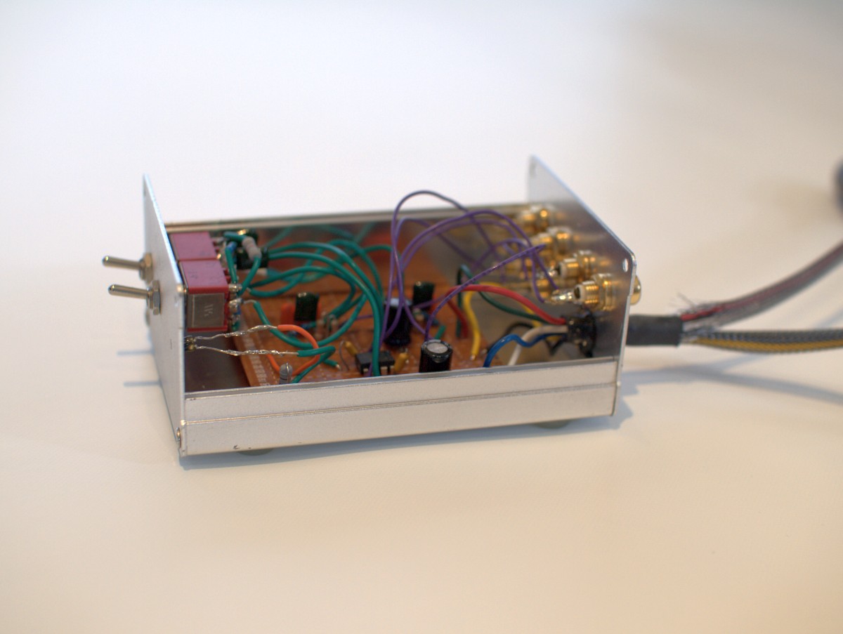
The obvious workaround is a dedicated crossfeed effect unit. The circuit is based on the work of Chu Moy, who over the years has made a few notable contributions to hobbyist hi-fi headphone audio. Because the effect unit was destined to be connected in parallel with the input of my living room stereo, I added an op-amp buffer to the input for pedantic audiophile thoroughness. The whole unit is powered by a loop through connection from the power supply of the Gilmore Lite, which means one less power cord at my desk and more than a few dollars saved.
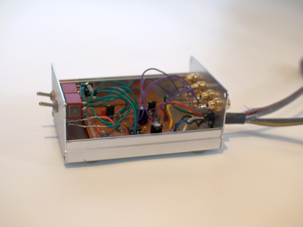
Headphone Crossfeed

Headphone Crossfeed

I actually built two identical units, as a friend of mine with the same headphone amp had the same concerns to address. A quick fun build on protoboard with components bought retail from Lee’s Electronics, a handy local source for electronics parts.

 Bi-Amped Stereo, with active crossover and phono preamplifier

stereo preamp reclaimed chassis with phono input active crossover regulated power supply

File this under ‘needless complexity,’ it’s another metal and silicon manifestation of pedantic audiophilia. Rod Elliot describes the rationale behind active bi-amplification in a series of articles on his site, and that site is also the source for the circuit schematics used in this project. A bi-amplified system with active crossovers has more headroom, simpler loads for the amplifier, and better crossovers than a conventional 2 channel stereo with passive crossovers in the speaker cabinet, which in theory results in superior sound, though I personally have no objective way of measuring the sound quality. I find it convincing that many powered studio monitors use this principle, so, well, why not?

This was another budget, experimental project, though parts costs add up quickly. The chassis is reclaimed, slightly spruced up with a new sheet metal face. All circuits are handmade on protoboard. The relay, visible mid-rear in the image above, grounds the outputs when the power goes off to prevent big transients when the op-amps shut down from going to the power amp and making the speakers do alarming things. This preamp provides signal to a handmade 4 channel chipamp to actually move air and make sound.

shop stereo

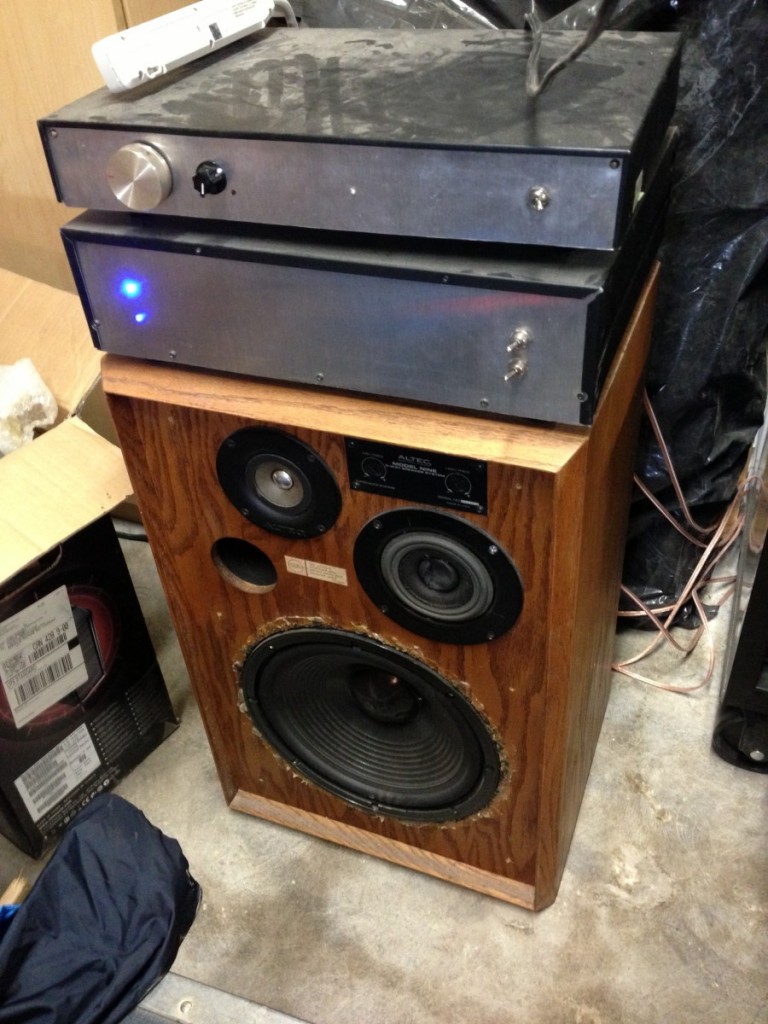
This project is currently driving some vintage Altech Lansing Model 9’s with replacement found-in-the-alleyway 12″ drivers, with crossovers removed and new double binding posts added. This system is now demoted to use as a big, loud, ugly, but good sounding shop stereo, as I’ve gone to some much sleeker Paradigm Monitor 7s and a NAD amplifier (with wonder of wonders, a remote volume control) as my home hi-fi.

Phono preamp

Since i’m not about to bother with spinning vinyl in a dusty, crowded, and vibration-addled shop space, and my newly purchased home stereo came sans a phono channel with RIAA equalization and extra gain for playing records, I snipped the phono preamp module from my handbuilt preamp/active crossover and slapped it into a case for use at home. For the ultimate in a low-noise power supply, as well as ease of assembly, it runs off of 2 9V batteries.
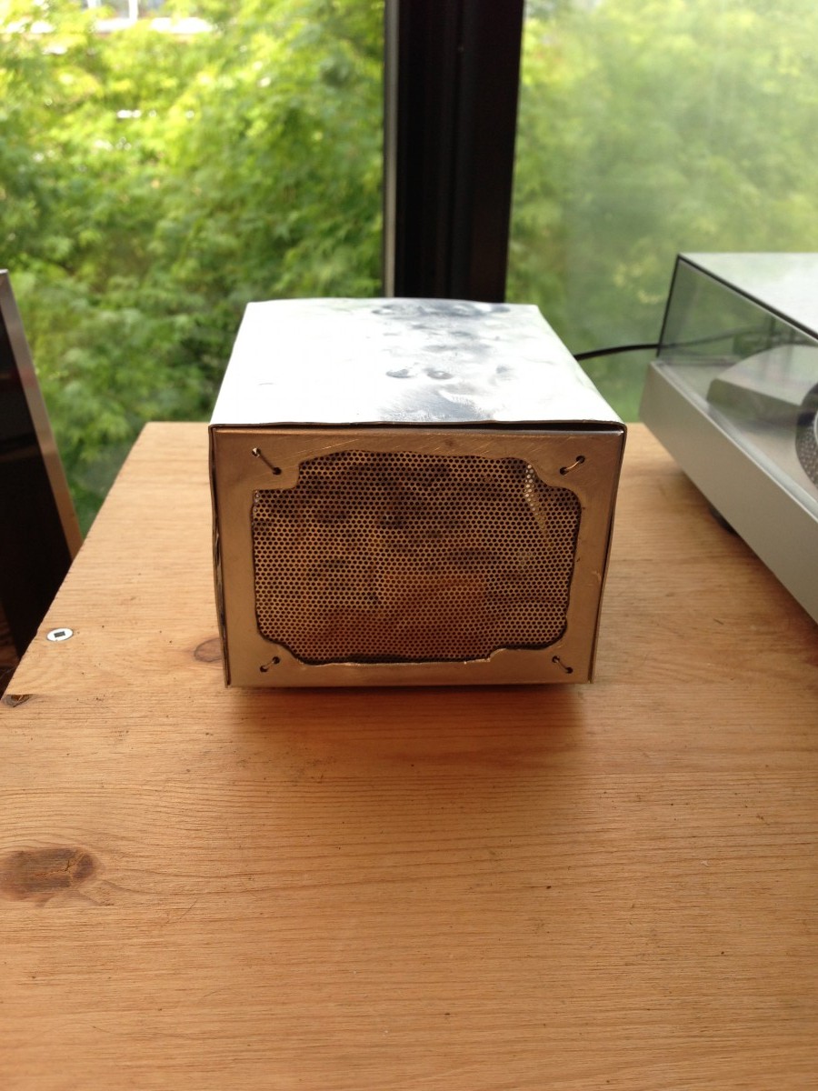
phono preamp

phono preamp

The case was bashed out of scrap material and distressed to give it a more exotic appearance, as a fun and hasty departure from the more typically modern, clean designs I tend toward. Power LED’s backlight the mesh, but they’re almost unphotographically dim since I’m trying to conserve battery power in this instance. I may rebuild this in a more substantial, finished, and wall-powered form in the future, but for now it gets me listening to my vinyl collection again and adds some whimsy to the home setup.

I’m pretty happy with my current setups, at my desk, in my living room, and in the shop, so if there’s any tweaking and upgrading to be done, it will be focused on proper speaker positioning and room acoustic treatments. I have experimented with homemade bass traps but decided the results were negligible in the room I’m listening in, though many spaces do benefit from some acoustic dampening…. although, it would be nice to listen to music or podcasts when soaking in the tub, and I’ve got some LM380 power amplifier chips floating around in my parts drawer, so probably the next project is a custom bathroom mini system because, well, why not?

Lift Up Storage Bed

Once again, I’ve been called upon to help maximizing space in a small dwelling. The space under a bed is an obvious candidate for storage, but a conventional steel bed frame and box spring consume all that, and even better designed beds that replace the pointless box-spring with supporting slats can make it hard to access the space beneath.

Because the client wanted to store 6 pairs of skis specifically, the obvious strategy was to build a lift-up storage bed. There are commercially available units with a similar method of operation, but they have extra material, a larger footprint, and a higher sticker price than the ‘you cover the costs and I’ll build my portfolio’ rate that I charge my friends.

The finished bed is made of spruce dimensional lumber, with stained and varnished laminated pine panels for sides. Definitely budget materials, but with enough sanding, patience, and coats, the resulting finish is richly coloured and smooth. The final exterior design element of note is a toe-kick recess along the floor on three sides to prevent stubbed toes and give the bed a floating appearance, which helps to lighten the look of the wide panels.

finished storage bed

The mechanism uses off-the-shelf automotive trunk struts, and casters and bar stock  from the hardware store. Large diameter bolts keep the pivots square to the frame, even with big stacks of washers used for horizontal spacing and alignment of the strut and linkage. Nylok nuts ensure it won’t loosen with use.The upper platform is reinforced with flatbar since it is subjected to constant tension from the struts when the bed is in the down position. The linkage moves the platform forward as it is lifted so the top edge of the mattress doesn’t hit the wall behind the bed.

lift mechanism

I designed the linkage geometry so that the strut force lifts the frame progressively. In the lowered position, the strut is held compressed but mostly places the platform frame in tension, with little force acting downward. In the upper position, the arm swings out and the strut acts quite directly to hold the platform up. In this way the bed stays down on its own, but also easily supports a mattress and bedding in the up position. When the bed is lifted it initially bears down on a caster (obscured in the picture above) and rolls along the top of the rail, until it lifts up enough to cantilever off of another caster rolling along the bottom, which is what prevents it from tilting forward.  Operating the bed is quite ergonomic since the strap handles used to lift it are at the foot of the platform and the casters and linkage which bear the weight are near the head of the bed.

lifty-lifty: look Ma, no hands!

The weight of the platform, mattress, and slumbering bed-users is borne to the floor by 8 solid wood posts on the periphery, leaving the entire middle section unobstructed for storage, and the wide side panels prevent any racking of the frame, resulting in a very stable bed.

The footprint of the bed is only a few centimeters wider on all sides than the mattress itself. This was a critical design parameter as the bedroom door swings within a scant few millimeters of the frame.

rescued space put to work, with all that stuff hidden nicely from view

The end result fits the room, looks clean, stores a ridiculous amount of gear, and is easy operate.  I look forward to tackling similar projects when the budget allows for some custom machined metal parts to keep tolerances tighter and simplify final assembly. In the meantime, making due with the tools and parts at hand is a fun part of the challenge.